I am at the point now where I can pretty much repair everything of a Leica M3 (mostly because you can find the service manual for it AND Leica still sells spare parts for it), with the exception of the rangefinder.
The viewfinder/rangefinder assembly is the one part that not even Leica repairs anymore, they simply change the whole assembly, retrofitting M3s with the MP’s rangefinder (for more than $900). For that reason, I started playing around with the idea of learning how to fix the most common problem on the rangefinder of an M3: separation.
One of the many parts of the viewfinder/rangefinder assembly is a beamsplitter: a cube of glass with a semi-reflective diagonal that is used to merge the viewfinder’s image and the rangefinder’s patch. Cube beamsplitters are simply two triangular prisms that are glued together, and one of them is coated with a semi-reflective layer of material. In the case of the Leica M3, it seems that they used gold. If you deposit a layer of gold (or silver, aluminium, et cetera) thin enough, part of the light will go through it, and part of it will be reflected. The most common problem with M3s’ beamsplitters is that after a few decades they separate, meaning that the glue holding the two prisms together comes loose. When that happens, the viewfinder/rangefinder is unusable. The solution is to take the assembly out of the camera, and re-coat one of the prisms with a semi-reflective material, and re-glue the beamsplitter back together. Getting the beamsplitter out of the rangefinder assembly is pretty hard: whatever glue they used to set it in place is strong and did not weakened in any of the solvents that I tried, not even acetone. My suggestion is that you slowly and carefully scrape it off, using drill bits to remove it from the holes it is in.
After a few attempts, I was able to deposit a semi-reflective layer of silver on one of the prisms, and glue the beamsplitter back together. The result is NOT pretty, but it works. The hardest part of the process is to obtain a uniform layer of silver, while making sure that the amount of reflected light is roughly the same as the amount of transmitted light. My initial idea was to do the deposition while controlling the amount of light going through the prism (with a light-meter app on my phone) and stop it once the light was cut in half. This turned out to be easier said than done, and I eventually settled on a “try again” approach. Once you get the hang of it, depositing silver on a small piece of glass is done in about 5 minutes, and with a UV glue putting the prisms together is even faster. It took me about 10 tries to get an acceptable deposition of silver, and I stopped mostly because I was going on a trip the next day and I really wanted to bring that camera with me to shoot pictures. To deposit silver on one of the prisms, I used the mini-kit available at angelgilding, and I used a UV/blue curing optical adhesive from Norland, NOA85V. My tips for silvering are:
- Use only glassware and make sure it’s clean. I tried to use some plastic container I had around to hold the chemicals and the glass during the deposition, and I would always get a brown cast on the silver coat. When looking through the viewfinder/rangefinder assembly I would see the RF patch, but the whole image was dark and brown-ish. My guess it that the plastic the container was made of interacted with the chemicals and contaminated the silver deposit.
- Use a stopwatch to record the amount of time the prism spends in the chemicals. In my case I figured it took around 3 minutes and a half to get a silver coating that reflected and transmitted the same amount of light (roughly).
- Keep an eye on the temperature. Like all chemical reactions, temperature is going to affect the deposition rate. Instead of measuring the temperature and trying to control it, do all the tries and deposition in one day, so that you know that your chemicals were roughly at the same temp the whole time. I did my final 4/5 attempts in one afternoon, so I knew that leaving the prism in for an extra 30 seconds would give me a thicker coat of silver, cause I knew the temperature was roughly the same as before.
- Be patient. It’s gonna take some time, some cursing, some sweating. Be ready to be disappointed and to improvise. Once you see the pictures of my result, you’ll see that you don’t need to achieve perfection to get something that works well.
- Don’t be clumsy. Once you get the deposition that you like, be aware of where you put your fingers! The silver that is chemically deposited on the glass surface is VERY delicate, and just touching it is going to remove it. Do not touch the surface once you’re happy with it. No cotton balls, not acetone to “clean it one last time before I glue it”. Just use a hand blower to remove dust if you see any on it, but no physical contact whatsoever.

The initial condition. You can see that the prisms is in really bad shape. I used this prism in another RF assembly, because this one was too rusty to be useful.

The two red rectangles are highlighting the dreadful glue that is impossible to remove with solvents

Remove the set screws, one on top and the other one at the bottom

As you can see, I drilled out the glue and, carefully, I was able to wiggle the beamsplitter out

Don’t worry, there is more glue at the bottom

One of the prisms that make up the beamsplitter

I used hot glue to construct a holder for the chemicals

I added a “base”, made of hot glue as well

Building the last of the four sides

The finished product

The finished product, with electrical tape to stop stray light from entering. My idea was to set this whole contraption on top of the camera of my phone, and use that to measure the amount of light coming in. I would then pour the chemicals in this “cup”, and wait for the light meter reading to cut in half. At that point I’d know that the deposited silver was semi-reflective, and I’d stop it. It did not work, and the cup was leaking chemicals all over (yes, I did use a plastic foil to protect my phone, so no damage done)

I managed to get a silver coat with this method, but it turned out to be too thin, and the RF patch was not bright enough!

After the silver coating, I removed the walls of the hot glue “cup”

I then used the UV adhesive and cured it under UV light (Yes, I am using a nail polish curing light, and no, it does not work very well)

I used NOA85V because that adhesive cures with UV light and blue light as well. The UV light that this nail polish machine gives out is not suitable to use with the NOA60 or other more general purpose Norland products

The finished product, first try. Notice that the alignment of the two prisms wasn’t that good, but hey, givemeabreak

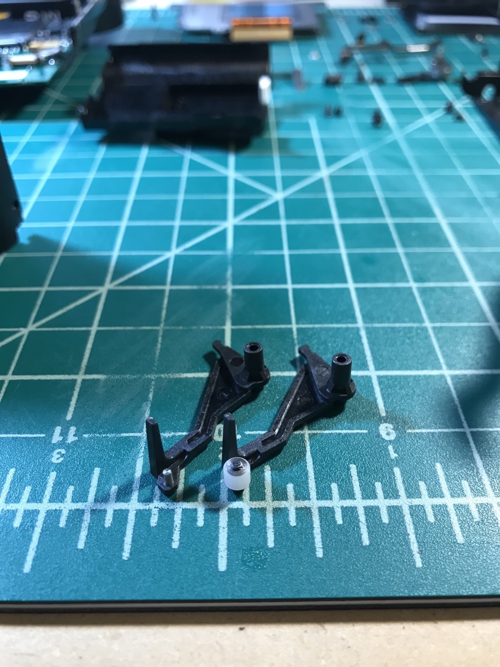
Added the negative lens, curing this bond too

The prisms masked and ready to be painted black, in order to block stray light

In my first try I used the black paint that came in the mini silvering kit from angelgilding. Don’t use it!

Whatever solvent their paint is based on, it attacked the NOA85V adhesive and ruined my coating. You can clearly see that the solvent worked its way between the prisms

That had an impact on the usability of the beamsplitter, though you can see that it is not too bad after all

Another shot where you can see the damage done by the angelgilding black paint. Just use something else

This is a shot of my last attempt, the successful one. Unfortunately, I did not take pictures of the deposition process, it happens fast (3 or 4 minutes) and I was using my phone to time it. You can see the setup that I used in the background though: the beaker that I used to deposit the silver on the prisms is completely covered with silver now, and to the left of it you can see the rinse water container

Curing the beamsplitter. You can see that I used a base made with hot glue to keep the prisms up. This allowed me to put a drop of glue on the face of it, then put the other prism on top and, if you make it really horizontal, the prism on top won’t slip away and you’ll have time to align them perfectly. Then when you’re happy with the alignment you come in with the light and cure the glue.

The beamsplitter assembled (including the negative lens) and painted. This time I used testors enamel, and it did not attack the NOA85V, though it took longer to cure and I put two coats on it (24 hours cure time, minimum)

As I mentioned, keep your fingers off the silver deposition! Although it looks very sloppy and unusable, it actually works quite nice

The beamsplitter back where it belongs. I know it looks bad, but trust me, even something like that works and you won’t notice the unevenness of the coating when you look through the viewfinder
The initial condition. You can see that the prisms is in really bad shape. I used this prism in another RF assembly, because this one was too rusty to be useful.
The two red rectangles are highlighting the dreadful glue that is impossible to remove with solvents
Remove the set screws, one on top and the other one at the bottom
As you can see, I drilled out the glue and, carefully, I was able to wiggle the beamsplitter out
Don’t worry, there is more glue at the bottom
One of the prisms that make up the beamsplitter
I used hot glue to construct a holder for the chemicals
I added a “base”, made of hot glue as well
Building the last of the four sides
The finished product
The finished product, with electrical tape to stop stray light from entering. My idea was to set this whole contraption on top of the camera of my phone, and use that to measure the amount of light coming in. I would then pour the chemicals in this “cup”, and wait for the light meter reading to cut in half. At that point I’d know that the deposited silver was semi-reflective, and I’d stop it. It did not work, and the cup was leaking chemicals all over (yes, I did use a plastic foil to protect my phone, so no damage done)
I managed to get a silver coat with this method, but it turned out to be too thin, and the RF patch was not bright enough!
After the silver coating, I removed the walls of the hot glue “cup”
I then used the UV adhesive and cured it under UV light (Yes, I am using a nail polish curing light, and no, it does not work very well)
I used NOA85V because that adhesive cures with UV light and blue light as well. The UV light that this nail polish machine gives out is not suitable to use with the NOA60 or other more general purpose Norland products
The finished product, first try. Notice that the alignment of the two prisms wasn’t that good, but hey, givemeabreak
Added the negative lens, curing this bond too
The prisms masked and ready to be painted black, in order to block stray light
In my first try I used the black paint that came in the mini silvering kit from angelgilding. Don’t use it!
Whatever solvent their paint is based on, it attacked the NOA85V adhesive and ruined my coating. You can clearly see that the solvent worked its way between the prisms
That had an impact on the usability of the beamsplitter, though you can see that it is not too bad after all
Another shot where you can see the damage done by the angelgilding black paint. Just use something else
This is a shot of my last attempt, the successful one. Unfortunately, I did not take pictures of the deposition process, it happens fast (3 or 4 minutes) and I was using my phone to time it. You can see the setup that I used in the background though: the beaker that I used to deposit the silver on the prisms is completely covered with silver now, and to the left of it you can see the rinse water container
Curing the beamsplitter. You can see that I used a base made with hot glue to keep the prisms up. This allowed me to put a drop of glue on the face of it, then put the other prism on top and, if you make it really horizontal, the prism on top won’t slip away and you’ll have time to align them perfectly. Then when you’re happy with the alignment you come in with the light and cure the glue.
The beamsplitter assembled (including the negative lens) and painted. This time I used testors enamel, and it did not attack the NOA85V, though it took longer to cure and I put two coats on it (24 hours cure time, minimum)
As I mentioned, keep your fingers off the silver deposition! Although it looks very sloppy and unusable, it actually works quite nice
The beamsplitter back where it belongs. I know it looks bad, but trust me, even something like that works and you won’t notice the unevenness of the coating when you look through the viewfinder
As you can see, my final result is not pretty, but when I look through the viewfinder I don’t notice the bad silver coating: that’s because the silver is not where the image is formed! For example, you will see any speck of dust that is on the frameline mask of the rangefinder, but you won’t see that big spot where I accidentally remove silver from the prism. I hope this help anyone that is trying to do the same repair.